The
LOCO (LOndon CO-axial) network was installed in the 1960s as a
replacement for the 'Balanced Pair' network installed originally in the
early 50s.
The original Balanced Pair consisted of 150lb/mile copper cable pairs and standard transformers could be used to convert from the unbalanced TV signals to the balanced signal for the external cable. As for audio - but at a somewhat higher frequency - the transformer at the receiving end not only restored the unbalanced signal but also served to cancel out interference on the pair.
It was only really suitable for black and white 405 line TV and the arrival of 625 lines and colour required something better.
Early Outside Broadcasts to Alexandra Palace - like boxing from Tottenham Town Hall - using ordinary telephone pairs, required repeater equipment to be installed in the cafe half-way up the hill at Alexandra Palace!!
It is also worth noting however that, even before the 8Mb/s ADSL signals were carried over ordinary telephone pairs, video had been passed down them over relatively long distances using modern equipment. The regular TV broadcasts from the London Hippodrome/Talk of the Town to a GPO exchange in Chinatown were provided on standard telephone pairs for some years even into colour TV times.
Some Coaxial cables had been installed around London as early as the Coronation in 1953 but there had been problems with electrical interference from earth currents flowing down the outer sheath which was originally earthed. Passing Trams with their large current spikes caused particular problems.
As video signals theoretically go down to almost DC, a carrier system was usually installed on these coaxial cables to raise the video signals above the 50c/s earth currents. Alternatively (as in the Coronation) two separate co-routed coaxial cables were used with their centre conductors used to provide a balanced, isolated pair.
The earth current problem was overcome partly by isolating the outer conductor from earth, so the coaxial cables were strictly a triaxial cable as they consisted of three conductors! The inner signal wire, the coaxial outer signal return screen and an outer protective earthed screen.
Also a device called a 'Stop Coil' was invented. This consists of a long length of fairly thin coaxial cable wound on a very large and heavy (believe me - they also make good door stops) metal core.
As long as the wanted TV signal goes down the coaxial 'inner' and returns down the coaxial 'outer', there is no net effect of the large inductance of the coil of cable around the metal core except for a slight high frequency loss.
However if we assume that any interfering signal is induced equally in the inner and outer and travels in the SAME direction, there will be a large series inductance caused by the transformer effect of the cable around the metal core.
Most interference is mains bourne with a fairly low frequency component of 50 and 100c/s and so the large inductance combined with the cable capacitance will form a high pass filter and cause considerable attenuation to unwanted low frequency earth currents. As long as the outer conductor is not earthed and the resistance of the inner and outer are not too dissimilar, a very hig degree of rejection can be obtained.
It is worth noting that it is best to install stop coils at both ends of a cable and that two in series provide very little extra improvement.
The GPO had installed 1" coaxial cables throughout the UK in the late 1940s and early 1950s for television transmissions. These cables were designed to be able to carry colour when it was introduced. At the time, the 405 line system required about 3Mc/s bandwidth and it was thought that colour, with three separate signals - red, green and blue - would require at least 9Mc/s. Using the valve equipment available at the time, it was necessary to amplify the signal about every 9 miles for black and white and thus about every 3 miles for colour. The cable was therefore brought up into a suitable GPO premise every 3 miles throughout the length and bredth of the country but only equalised every 3rd premise.
As the equipment was not that reliable, each equalising point was equipped with 'main' and 'spare' equipment chains with change-over relays controlled from the GPO Tower in London.
By the time the LOCO was installed, 625 line PAL TV had been established as the UK standard and this only requires about 5.5Mc/s for acceptable colour.
As the distances involved were also much less and equalisation and amplification equipment had improved considerably, the LOCO was installed using two 3/8" coaxial cores in one outer lead cable sheath. The coaxes were paper insulated within this cable but brought out by a lead joint to two separate cables at the ends.
Obviously 2 round coaxes inside a round outer sheath leave gaps. These gaps were filled with standard 40lb/mile telephone pairs arranged in both quad formation and as single twisted pairs in groups. As these pairs did not get mixed in with the pulse dialling telephone system, but often went directly between the Outside Broadcast point and the BBC, these pairs were very useful as they provided a very high quality path for the sound signals associated with the television signal and a lower quality path for intercommunication signals.
The network included remote switching relays, controlled over one of the telephone pairs from BBC Broadcasting House. Either +80v or -80v relative to earth was sent on one leg to operate special relays and a return earth on the other leg showed the state of the relay.
The relays were actually installed in a pair and wired so that both the inner conductor and the outer coaxial sheath were switched to avoid a spare 'leg' hanging across the cable. Also the 'switched away' coax was terminated in 75ohms to minimise any residual crosstalk in the relay box.
Most relays were installed in the GPO cabinets by the street but a few were in either GPO or BBC premises. However all relay boxes were made to a similar specification wether used outside or in so that only one type of spare was required.
All this of course is ancient history!!
The inter-regional coaxial circuits were firstly replaced by microwave links between GPO masts up and down the country. These were shared with long-distance telephony circuits over most routes. Equipment failure was covered by provision of spare microwave channels - usually provided 'end-to-end' between major centres. Monitoring was provided to switch over to a spare in case of failure. The GPO engineers at the Tower in London were heard to say that they much preferred the change-over relay system as it gave them full fault control!
These spare microwave circuits were often made available to Broadcasters (at a cost) to enable them to route outside broadcasts around the country. It was also possible at some places to'inject' a temporary Outside Broadcast microwave into these GPO circuits.
Nowadays all long-distance communication is on fibre optic cables. Recently digital transmission has enabled thousands of telephone calls or dozens of television signals to be sent over a single fibre. Many thousands of miles of fibre now encircle the earth.
For Outside Broadcasts, some London locations and most of the sports grounds and places of importance throughout the country, have now been equipped with permanent fibre connections either permanantly rented by the Broadcasters or with spare fibres owned by BT which are equipped with the necessary terminal equipment as required.
For news inserts it is even possible to get 'matchbox size' analogue to digital fibre converters (from companies like http://www.bluebellcomms.co.uk/index.php ) so a cameraman may plug his camera direct to a fibre and so there is no need to keep an old analogue coaxial 'LOCO'
However time still moves on and there is now an increasing use of Satellite transmission for Outside Broadcasts. This has the advantage of not requiring any permanent infrastructiure and direct transmission to the Broadcaster's premises in may cases.
The cost of renting the 'space segment' has also plummeted with digital transmission requiring less bandwidth and a plethora of available satellites and uplink companies.
However the LOCO was there first!!
Now view on!!
As always 'click' on image for larger version
 Back to index page
MJ 121110
The original Balanced Pair consisted of 150lb/mile copper cable pairs and standard transformers could be used to convert from the unbalanced TV signals to the balanced signal for the external cable. As for audio - but at a somewhat higher frequency - the transformer at the receiving end not only restored the unbalanced signal but also served to cancel out interference on the pair.
It was only really suitable for black and white 405 line TV and the arrival of 625 lines and colour required something better.
Early Outside Broadcasts to Alexandra Palace - like boxing from Tottenham Town Hall - using ordinary telephone pairs, required repeater equipment to be installed in the cafe half-way up the hill at Alexandra Palace!!
It is also worth noting however that, even before the 8Mb/s ADSL signals were carried over ordinary telephone pairs, video had been passed down them over relatively long distances using modern equipment. The regular TV broadcasts from the London Hippodrome/Talk of the Town to a GPO exchange in Chinatown were provided on standard telephone pairs for some years even into colour TV times.
Some Coaxial cables had been installed around London as early as the Coronation in 1953 but there had been problems with electrical interference from earth currents flowing down the outer sheath which was originally earthed. Passing Trams with their large current spikes caused particular problems.
As video signals theoretically go down to almost DC, a carrier system was usually installed on these coaxial cables to raise the video signals above the 50c/s earth currents. Alternatively (as in the Coronation) two separate co-routed coaxial cables were used with their centre conductors used to provide a balanced, isolated pair.
The earth current problem was overcome partly by isolating the outer conductor from earth, so the coaxial cables were strictly a triaxial cable as they consisted of three conductors! The inner signal wire, the coaxial outer signal return screen and an outer protective earthed screen.
Also a device called a 'Stop Coil' was invented. This consists of a long length of fairly thin coaxial cable wound on a very large and heavy (believe me - they also make good door stops) metal core.
As long as the wanted TV signal goes down the coaxial 'inner' and returns down the coaxial 'outer', there is no net effect of the large inductance of the coil of cable around the metal core except for a slight high frequency loss.
However if we assume that any interfering signal is induced equally in the inner and outer and travels in the SAME direction, there will be a large series inductance caused by the transformer effect of the cable around the metal core.
Most interference is mains bourne with a fairly low frequency component of 50 and 100c/s and so the large inductance combined with the cable capacitance will form a high pass filter and cause considerable attenuation to unwanted low frequency earth currents. As long as the outer conductor is not earthed and the resistance of the inner and outer are not too dissimilar, a very hig degree of rejection can be obtained.
It is worth noting that it is best to install stop coils at both ends of a cable and that two in series provide very little extra improvement.
The GPO had installed 1" coaxial cables throughout the UK in the late 1940s and early 1950s for television transmissions. These cables were designed to be able to carry colour when it was introduced. At the time, the 405 line system required about 3Mc/s bandwidth and it was thought that colour, with three separate signals - red, green and blue - would require at least 9Mc/s. Using the valve equipment available at the time, it was necessary to amplify the signal about every 9 miles for black and white and thus about every 3 miles for colour. The cable was therefore brought up into a suitable GPO premise every 3 miles throughout the length and bredth of the country but only equalised every 3rd premise.
As the equipment was not that reliable, each equalising point was equipped with 'main' and 'spare' equipment chains with change-over relays controlled from the GPO Tower in London.
By the time the LOCO was installed, 625 line PAL TV had been established as the UK standard and this only requires about 5.5Mc/s for acceptable colour.
As the distances involved were also much less and equalisation and amplification equipment had improved considerably, the LOCO was installed using two 3/8" coaxial cores in one outer lead cable sheath. The coaxes were paper insulated within this cable but brought out by a lead joint to two separate cables at the ends.
Obviously 2 round coaxes inside a round outer sheath leave gaps. These gaps were filled with standard 40lb/mile telephone pairs arranged in both quad formation and as single twisted pairs in groups. As these pairs did not get mixed in with the pulse dialling telephone system, but often went directly between the Outside Broadcast point and the BBC, these pairs were very useful as they provided a very high quality path for the sound signals associated with the television signal and a lower quality path for intercommunication signals.
The network included remote switching relays, controlled over one of the telephone pairs from BBC Broadcasting House. Either +80v or -80v relative to earth was sent on one leg to operate special relays and a return earth on the other leg showed the state of the relay.
The relays were actually installed in a pair and wired so that both the inner conductor and the outer coaxial sheath were switched to avoid a spare 'leg' hanging across the cable. Also the 'switched away' coax was terminated in 75ohms to minimise any residual crosstalk in the relay box.
Most relays were installed in the GPO cabinets by the street but a few were in either GPO or BBC premises. However all relay boxes were made to a similar specification wether used outside or in so that only one type of spare was required.
All this of course is ancient history!!
The inter-regional coaxial circuits were firstly replaced by microwave links between GPO masts up and down the country. These were shared with long-distance telephony circuits over most routes. Equipment failure was covered by provision of spare microwave channels - usually provided 'end-to-end' between major centres. Monitoring was provided to switch over to a spare in case of failure. The GPO engineers at the Tower in London were heard to say that they much preferred the change-over relay system as it gave them full fault control!
These spare microwave circuits were often made available to Broadcasters (at a cost) to enable them to route outside broadcasts around the country. It was also possible at some places to'inject' a temporary Outside Broadcast microwave into these GPO circuits.
Nowadays all long-distance communication is on fibre optic cables. Recently digital transmission has enabled thousands of telephone calls or dozens of television signals to be sent over a single fibre. Many thousands of miles of fibre now encircle the earth.
For Outside Broadcasts, some London locations and most of the sports grounds and places of importance throughout the country, have now been equipped with permanent fibre connections either permanantly rented by the Broadcasters or with spare fibres owned by BT which are equipped with the necessary terminal equipment as required.
For news inserts it is even possible to get 'matchbox size' analogue to digital fibre converters (from companies like http://www.bluebellcomms.co.uk/index.php ) so a cameraman may plug his camera direct to a fibre and so there is no need to keep an old analogue coaxial 'LOCO'
However time still moves on and there is now an increasing use of Satellite transmission for Outside Broadcasts. This has the advantage of not requiring any permanent infrastructiure and direct transmission to the Broadcaster's premises in may cases.
The cost of renting the 'space segment' has also plummeted with digital transmission requiring less bandwidth and a plethora of available satellites and uplink companies.
However the LOCO was there first!!
Now view on!!
As always 'click' on image for larger version
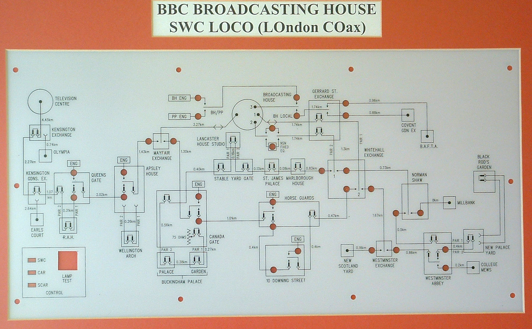 |
LOCO map in later years with News access points. |
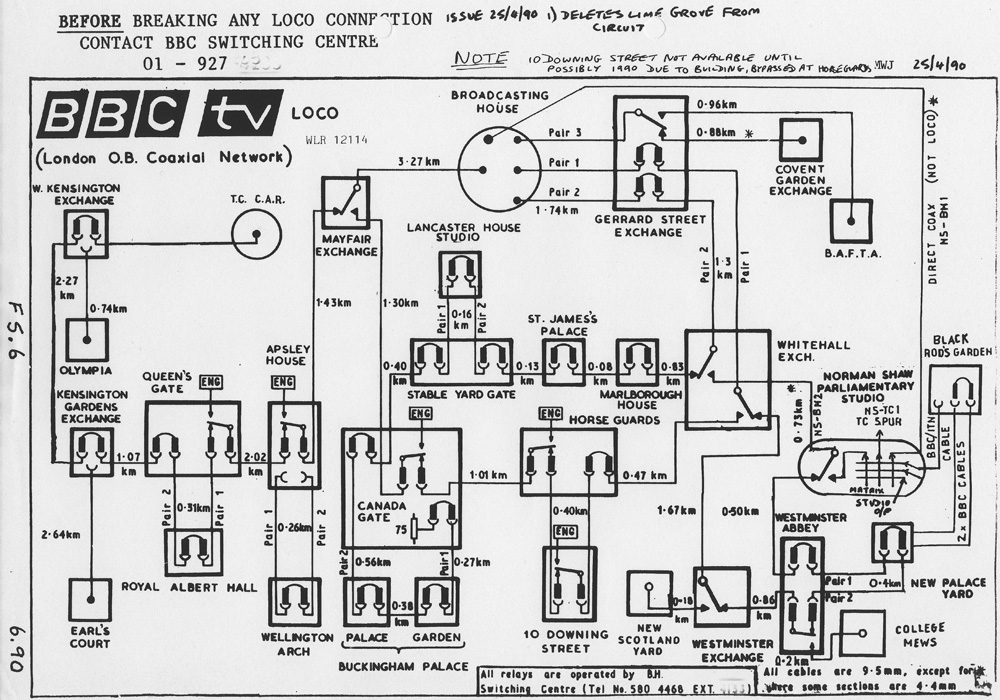 |
Earlier LOCO map around 1990 For my 'Around London by Tube' write-up click HERE (in pdf format) |
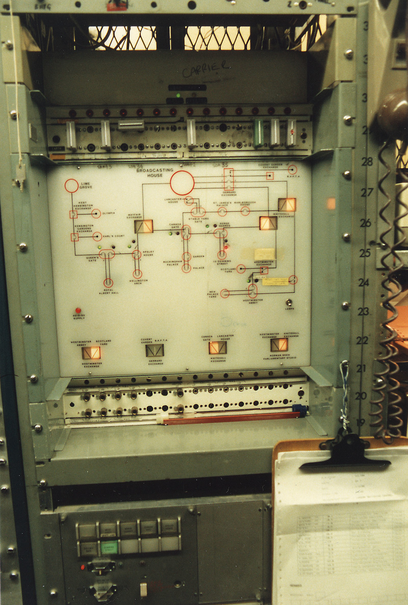 |
Original LOCO switch panel in Switching Centre. |
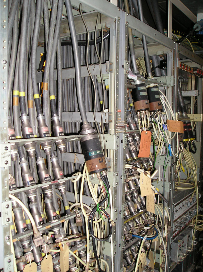 |
LOCO 3/8" coaxial cables leaving BBC at Broadcasting House |
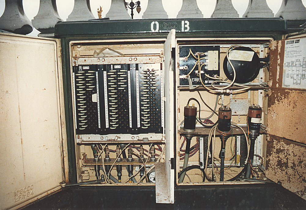 |
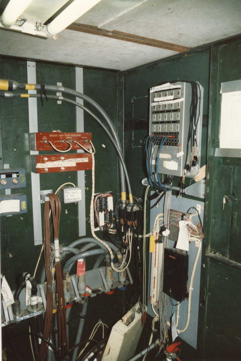
Canada Gate (opposite Buckingham Palace). The black boxes at the
right are 'Trunk Test Tablets' which terminate the telephone pairs
which surround the coax cables inside the outer sheath. They also serve
to 'build-out' the cable to make it more rugged by filling the spaces
between the round coax. They are known as 'interstitial pairs' as they
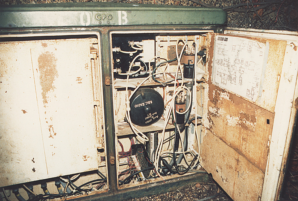
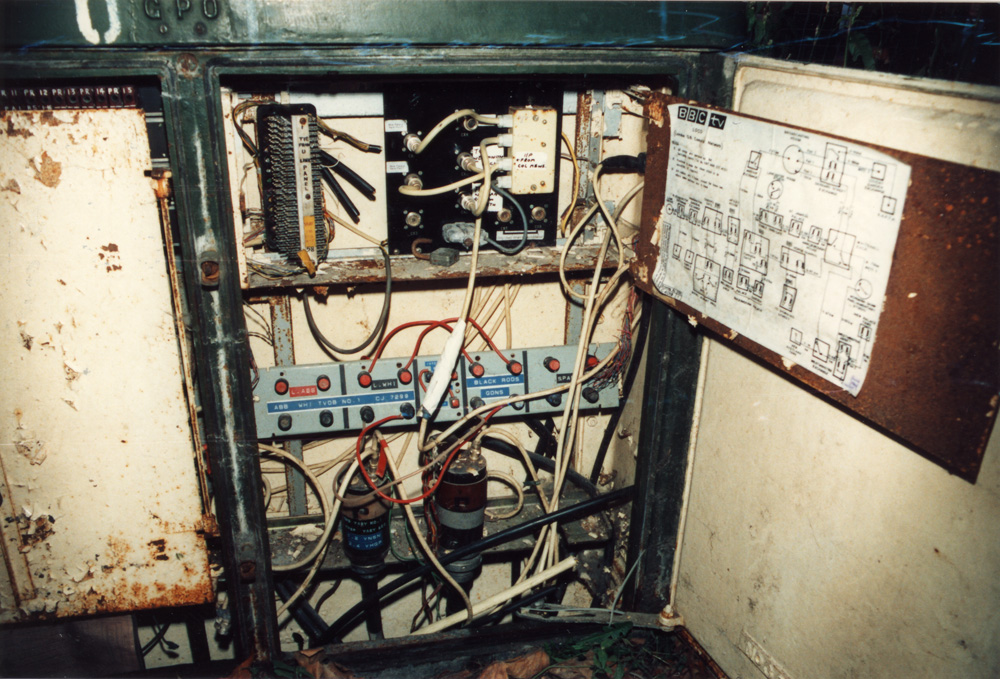
fill the interstices (i.e. gaps) in the cable. The round black object is a 'BT17' which is the official interface between GPO and broadcasters circuits. The main coaxial cables terminate lower right (3/8" LOCO - as put in in the early 1960s for colour) and lower left (0.174" coax put in later). They are then extended to a Relay panel to enable remote switching so that Outside Broadcasts can inject video into the network.Interestingly both the inner and outer of the coax is switched to maintain isolation from earth and having unused legs hanging across the line. Ordinary coax extends the circuits to a box on the outside so that broadcasters can connect without needing access to the GPO cabinet (which had a specially modified access key) |
 |
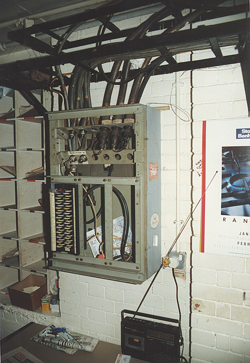
Number 10 Downing Street. The LOCO termination can be seen at the lower left hand side and the really shows well on it's little paxolin insulating plate. Directly below is a panel with teh Burndept GPO connectors which are directly soldered/lead wiped onto the lead cased co-ax cable. Below that is a GPO BT17 which is the termination for the Interstice Pairs in the Co-axial cable. (Interstice or Interstitial pairs are ordinary copper pairs used for extra communications and arranged in groups to fill up the spaces between the co-ax tubes and the outer lead sheath |
 |
Earls Court Exhibition Centre GPO frame Room. Large 'mains-type' connectors at top are the 150lb copper 'balanced pairs' used for video before coax was universally used. |
 |
Horseguards Parade. |
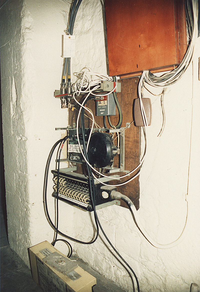 |
New Place Yard (Part of Palace of Westminster) From here, BBC cables went to Black Rod's Garden for coverage of State Opening of Parliament etc |
 |
Black Rod's Garden Box with cables to New Palace Yard to connect to GPO LOCO Co-axial cables |
 |
Black Rod's Garden Inside termination cabinet with video and audio tielines to Commentary positions etc within The Palace of Westmeinster |
 |
Mason's Yard (rear of Westminster Abbey). The red and black screw terminals are a 'Polyquad' cable. This is a high poundage, 2 pair cable with the pairs arranged opposite each other and twisted together. It was put in as a cheap replacement for coax for video use. Only really suitable for shortish distances and both pairs had to be used in the same direction to avoid croos-talk between the high level sending of the video in one direction and the low level receiving of the video coming back in the opposite direction.. The black thing with white stripe top left is the GPO 'tag block' used to interconnect and choose the allocation between the audio pairs in the LOCO cable and a connection block on the outside of the cabinet where the broadcaster connects his wires. |
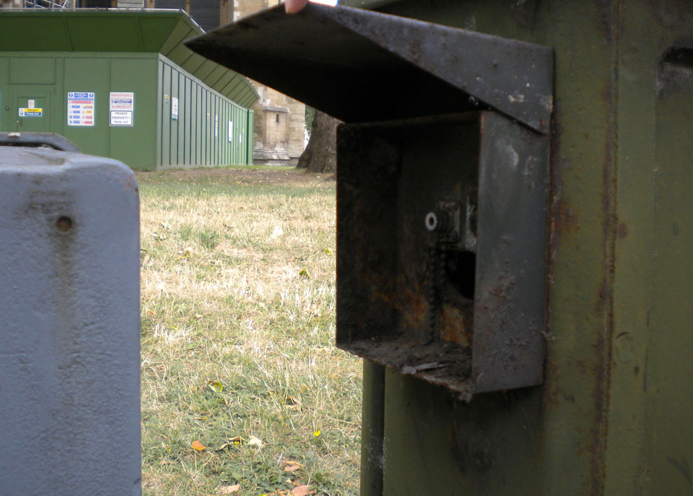 |
Masons Yard in 2010 I took this photo through the railings while showing people around Westminster. The F&E connector is well rusted away and the XLR doesn't look much better. And someone forgot to put the blanking cap back on the F&E |
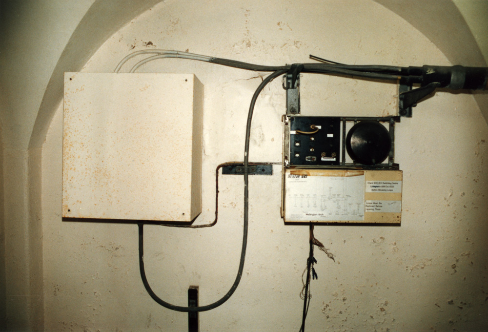 |
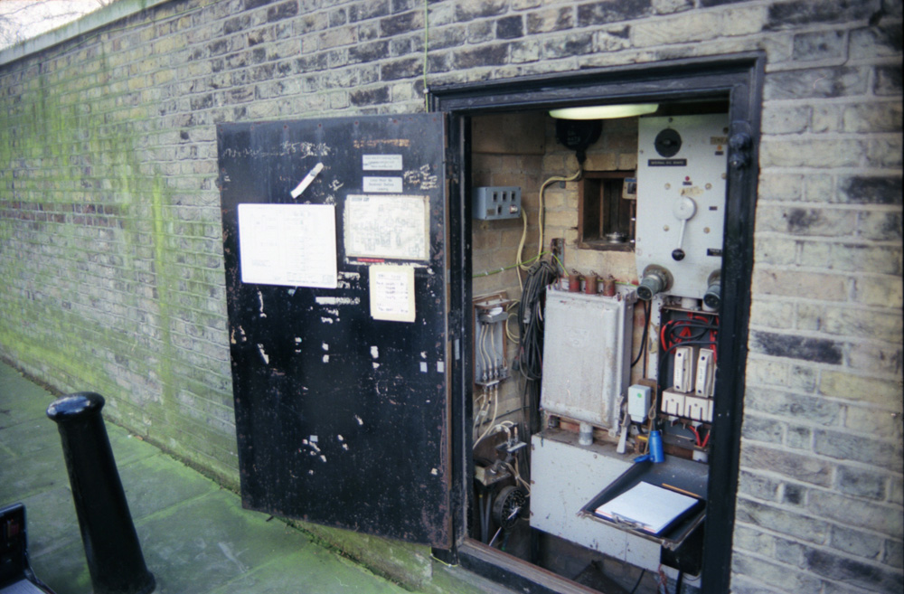
Termination inside the basement of Wellington Arch . 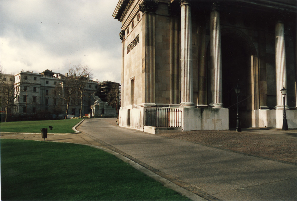 This was under Wellington Arch in the centre of Hyde Park Corner. The arch contained what must have been the smallest Police Station in London in those days but the whole arch is now open to visitors who may climb to the top for a view (for a price!) |
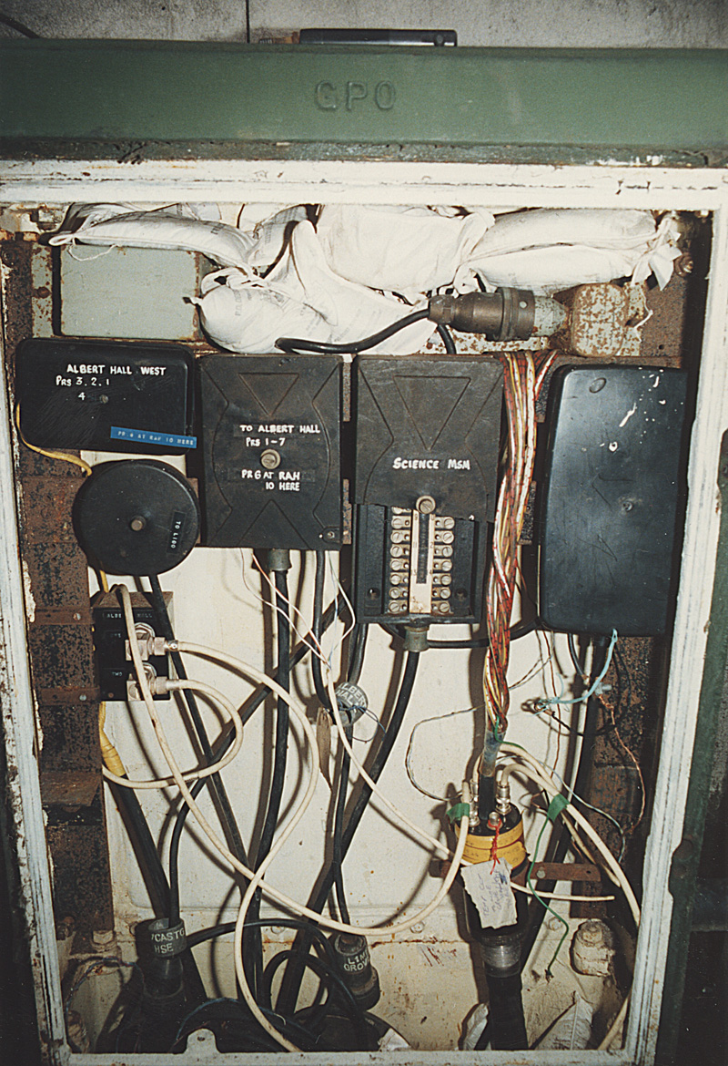 |
Queens Gate cabinet (inside the gates to Kensington Gardens opposite The Albert Memorial). This cabinet has some really old wires going direct to The Science Museum (long since disconnected!!) |
 |
Royal Albert Hall (West Termination). Showing new 0.174" cables (marked with yellow tape - as are all coaxial cables by GPO) which go to Queen's Gate. Also permanent copper wires back to BBC (on Right) |
Back to index pageMJ 121110